
Drone arm
Is a printed PA12 drone arm strong enough at full throttle?
You ask
Is this printed arm strong enough at full throttle, with a safety factor of 3?
Wobbl runs
$ wobbl run arm.py -m pa12 --target-sf 3 --fix "bolt holes d=3.2 and x<0" \ --load "25 N up at 150,0,15 @ top and within 15 of 150,0,15 rigid" \ --load "0.5 N*m +z at 150,0,15 @ top and within 15 of 150,0,15 rigid" \ --budget 600Checks
- passmesh convergence
- passforce balance
- passhand calculation
- warnsingularities
- passbolt bearing
- passunits and sanity
- passlarge deflection
- passload introduction
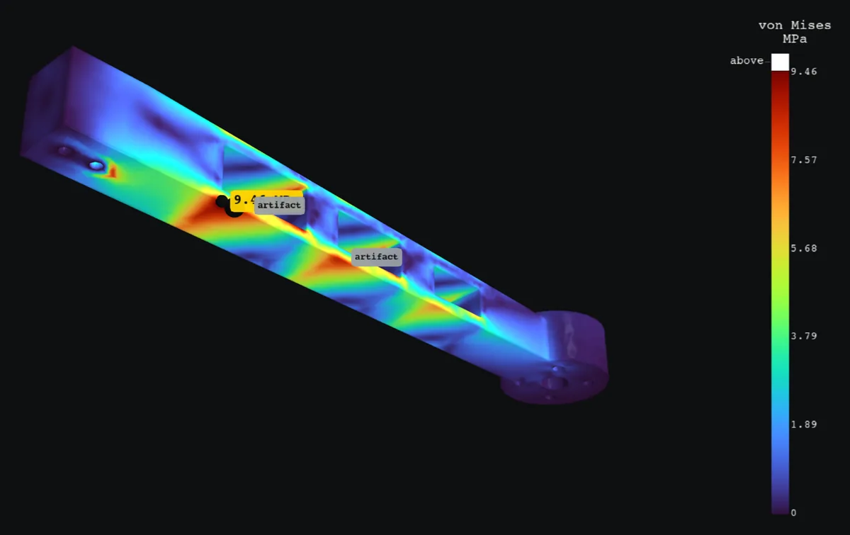
HOLDSPeak 9.46 MPa on face 2 at (25.8, -8, 0), safety factor 5.07 against yield (target 3). Confidence is medium.
- Peak stress
- 9.46 MPa
- Safety factor
- 5.07
- Target
- 3
- Confidence
- medium
Suggested fixes
- Round the sharp inside corner to a 1.71 mm radius
- Switch to PLA (3D printed)
summary.txt
HOLDS. Peak 9.46 MPa on face 2 at (25.8, -8, 0), safety factor 5.07 against yield (target 3). Confidence is medium. Confidence: medium. singularities: excluded from the answer: 14.4 MPa at a sharp inside corner (face 17) (a sharp corner: singular in theory, so the value depends on the mesh: 11.5 -> 14.6 -> 14.4 MPa); 9.94 MPa at a sharp inside corner (face 2) (a sharp corner: singular in theory, so the value depends on the mesh: 9.75 -> 9.89 -> 9.94 MPa); 9.7 MPa at a sharp inside corner (face 21) (a sharp corner: singular in theory, so the value depends on the mesh: 9.17 -> 9.38 -> 9.7 MPa). Wobbl reports the stress 4.12 mm or more away from these spotsMax deflection 4.22 mm at (165, -3.67e-15, 0).Material Nylon PA12 (SLS or MJF), limit 48 MPa; mass 40.43 g.Loads: 25 N up at 150,0,15 @ top and within 15 of 150,0,15 rigid; 0.5 N*m +z at 150,0,15 @ top and within 15 of 150,0,15 rigid. Fixtures: bolt holes d=3.2 and x<0. Checks: [pass] mesh convergence: von Mises stress settled: 9.44 -> 9.53 -> 9.46 MPa over 3 meshes, last change 0.7% [pass] force balance: reactions balance the loads to 0.00022% (forces) and 2.2e-05% (moments) [pass] hand calculation: beam theory through the critical section gives 6.69 MPa nominal; FEA peak is 1.42x that, a stress concentration of about 1.4 from the local shape [warn] singularities: excluded from the answer: 14.4 MPa at a sharp inside corner (face 17) (a sharp corner: singular in theory, so the value depends on the mesh: 11.5 -> 14.6 -> 14.4 MPa); 9.94 MPa at a sharp inside corner (face 2) (a sharp corner: singular in theory, so the value depends on the mesh: 9.75 -> 9.89 -> 9.94 MPa); 9.7 MPa at a sharp inside corner (face 21) (a sharp corner: singular in theory, so the value depends on the mesh: 9.17 -> 9.38 -> 9.7 MPa). Wobbl reports the stress 4.12 mm or more away from these spots [pass] bolt bearing: worst hole of fix1 (d 3.2 mm) carries 35.9 N sideways and 41.8 N along its axis; bearing stress 0.561 MPa, safety factor 85.60 on bearing [pass] units and sanity: part 188 mm across, peak strain 0.0056, max deflection 4.22 mm (2.2% of size): all plausible [pass] large deflection: deflection is large next to the wall thickness, so Wobbl solved the first mesh with large deflection theory too: the peak moves +2.3% and the deflection +0.1%; linear theory holds [pass] load introduction: the off part loads enter through a rigid attachment (the attached part does not flex). With a distributing coupling (the attached part adds no stiffness) instead, the governing stress is 9.46 MPa (1x, safety factor 5.07) at the same spot as the main answer, on the mesh already converged there. The verdict is the same either way Assumptions: - Linear elastic material and small deflections (no yielding redistribution, no buckling). - Nylon PA12 (SLS or MJF): E 1700 MPa, Poisson 0.39, von Mises vs yield 48 MPa (HP 3D High Reusability PA 12 datasheet; EOS PA 2200). - Loads are static and applied all at once; no impact, vibration or fatigue. - Printed part treated as isotropic at 100% infill; across the layers it is roughly 90% as strong. Pass --print-direction to check that. - Bolted holes are rigidly held over the hole and a washer sized ring (twice the hole radius). - Remote loads reach the part through a rigid attachment (the attached part does not flex). - Contact between separate parts, friction and preload are not modeled. Suggested fixes: - Stress piles up in the sharp inside corner. A fillet of 1.71 mm (about half the 3.42 mm wall) spreads it out. With that radius the peak is usually about 1.4x the 6.69 MPa beam stress, roughly 9.36 MPa (safety factor 5.13). - Stress stays about the same for the same shape and load, so PLA (3D printed) (50 MPa) gives safety factor 5.28. It is 2.1x as stiff, so deflection scales by 0.486. Other options: PETG (3D printed) (4.97), ABS (3D printed) (3.49). Images: stress: images/stress.png, zoom: images/zoom.png, safety: images/safety.png, deformed: images/deformed.png, convergence: images/convergence.pngReport: report.htmlAbout this example
This quadcopter arm is printed in PA12 by Multi Jet Fusion, a 150 mm tapered beam with three lightening windows, bolted into the frame through two holes in its root block. The motor sits on a 30 mm pad at the tip, and at full throttle it pushes up 25 N and twists the pad with 0.5 N m of reaction torque. The motor is stiff, so both loads go in through a rigid attachment on the pad.
The rule here for printed parts that vibrate is a safety factor of 3.
| Result | Value |
|---|---|
| Peak stress | 9.46 MPa on the underside of the arm below the first window, safety factor 5.1 against 48 MPa (meets the rule of 3) |
| Tip deflection | 4.2 mm |
| Mesh convergence | 9.44, 9.53, 9.46 MPa over three meshes |
| Hand calculation | beam theory through the critical section gives 6.69 MPa, and the local shape concentrates it 1.4x |
| Equilibrium | force and moment balance to 0.0002% |
| Large deflection | the arm bends a good share of its wall, so Wobbl also solves it with large deflection theory, which moves the peak +2.3% and shows linear theory holds |
| Load attachment | spread over the pad instead of rigid, the peak is the same 9.46 MPa at the same spot |
The windows are cut with square corners, and Wobbl excludes those corners from the answer as singular (they read 14.4 MPa on the finest mesh and depend on the mesh). Even that value meets the rule, but because it is more than one and a half times the answer the result is marked medium confidence. A 1 to 2 mm radius in the window corners is cheap in a printed part and makes the number trustworthy.
For a harder version of this question, a Warren truss arm, see the drone-arm-truss
validation case, which matches a
converged reference model to within 0.2%.
Run it yourself
$ git clone https://github.com/sohan-bhat/wobbl$ cd wobbl/examples/drone-arm && ./run.shThe part, the script and every output are in examples/drone-arm on GitHub.