
Motor mount
Do the ribs on a printed NEMA 17 mount earn their keep?
You ask
Will this printed PETG motor mount survive a 250 N belt pull?
Wobbl runs
$ wobbl run mount.py -m petg --print-direction z --fix "bolt holes d=5.5" \ --load "250 N down at 0,-15,31 @ normal +y and box -21,4,10,21,6,52 rigid"Checks
- warnmesh convergence
- passforce balance
- warnsingularities
- passbolt bearing
- passunits and sanity
- warnload introduction
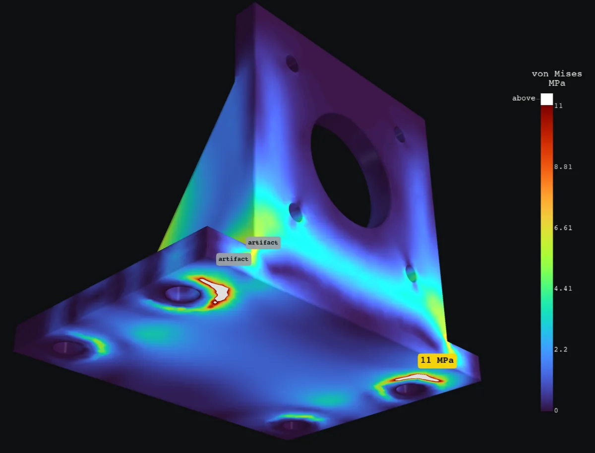
HOLDSPeak 11 MPa on face 19 at (24.7, 6.09, 1.96), safety factor 4.27 against yield (target 2.5). Confidence is medium.
- Peak stress
- 11 MPa
- Safety factor
- 4.27
- Target
- 2.5
- Confidence
- medium
summary.txt
HOLDS. Peak 11 MPa on face 19 at (24.7, 6.09, 1.96), safety factor 4.27 against yield (target 2.5). Confidence is medium. Confidence: medium. mesh convergence: von Mises stress (layer pull scaled by layer strength) still moving: 9.91 -> 11.1 -> 10.3 -> 11 MPa, last change 6.6% (stopped by level limit); expect about that much error. Even the highest value on any mesh plus that swing (11.8 MPa) leaves safety factor 3.99, so the verdict holds either way; singularities: excluded from the answer: 53.9 MPa at the edge of support fix1 (face 1) (set by the idealized support: 36 -> 47.7 -> 46.3 -> 53.9 MPa); 26.9 MPa at the edge of support fix1 (face 1) (set by the idealized support: 33.4 -> 23.5 -> 32.6 -> 26.9 MPa); 20.1 MPa where the rigid attachment load1 grabs the part (face 9) (set by the idealized support: 21.1 -> 15.5 -> 20.6 -> 20.1 MPa). Wobbl reports the stress 1.76 mm or more away from these spots; load introduction: the off part loads enter through a rigid attachment (the attached part does not flex). With a distributing coupling (the attached part adds no stiffness) instead, the governing stress converges to 18.8 MPa on face 5 at (21, 6.94, 37.3) (1.7x, safety factor 2.50) over 3 meshes refined around that peak: 19.2 -> 19.2 -> 18.8 MPa, last change 2.1%. The verdict depends on this assumption: check how the attached part really carries the load; the verdict depends on how the load enters the part (rigid attachment versus distributed); the answer assumes rigidMax deflection 0.399 mm at (-25, 0, 55).Material PETG (3D printed), limit 47 MPa; mass 39.36 g.Loads: 250 N down at 0,-15,31 @ normal +y and box -21,4,10,21,6,52 rigid. Fixtures: bolt holes d=5.5. Checks: [warn] mesh convergence: von Mises stress (layer pull scaled by layer strength) still moving: 9.91 -> 11.1 -> 10.3 -> 11 MPa, last change 6.6% (stopped by level limit); expect about that much error. Even the highest value on any mesh plus that swing (11.8 MPa) leaves safety factor 3.99, so the verdict holds either way [pass] force balance: reactions balance the loads to 3.4e-05% (forces) and 1.3e-05% (moments) [skip] hand calculation: no simple beam model applies (the governing point is not between the fixtures and the load, so no single section carries it) [warn] singularities: excluded from the answer: 53.9 MPa at the edge of support fix1 (face 1) (set by the idealized support: 36 -> 47.7 -> 46.3 -> 53.9 MPa); 26.9 MPa at the edge of support fix1 (face 1) (set by the idealized support: 33.4 -> 23.5 -> 32.6 -> 26.9 MPa); 20.1 MPa where the rigid attachment load1 grabs the part (face 9) (set by the idealized support: 21.1 -> 15.5 -> 20.6 -> 20.1 MPa). Wobbl reports the stress 1.76 mm or more away from these spots [pass] bolt bearing: worst hole of fix1 (d 5.5 mm) carries 68 N sideways and 147 N along its axis; bearing stress 2.46 MPa, safety factor 19.11 on bearing [pass] units and sanity: part 102 mm across, peak strain 0.0052, max deflection 0.399 mm (0.39% of size): all plausible [warn] load introduction: the off part loads enter through a rigid attachment (the attached part does not flex). With a distributing coupling (the attached part adds no stiffness) instead, the governing stress converges to 18.8 MPa on face 5 at (21, 6.94, 37.3) (1.7x, safety factor 2.50) over 3 meshes refined around that peak: 19.2 -> 19.2 -> 18.8 MPa, last change 2.1%. The verdict depends on this assumption: check how the attached part really carries the load Assumptions: - Linear elastic material and small deflections (no yielding redistribution, no buckling). - PETG (3D printed): E 2100 MPa, Poisson 0.38, von Mises vs yield 47 MPa (Prusament PETG technical data sheet). - Loads are static and applied all at once; no impact, vibration or fatigue. - Printed layers stack along z; pull across layers is judged against 70% of the in-plane strength. - Bolted holes are rigidly held over the hole and a washer sized ring (twice the hole radius). - Remote loads reach the part through a rigid attachment (the attached part does not flex). - Contact between separate parts, friction and preload are not modeled. Images: stress: images/stress.png, zoom: images/zoom.png, safety: images/safety.png, deformed: images/deformed.png, convergence: images/convergence.pngReport: report.htmlYou ask
The same mount without its ribs
Wobbl runs
$ wobbl run mount.py --param rib=0 -m petg --print-direction z \ --fix "bolt holes d=5.5" \ --load "250 N down at 0,-15,31 @ normal +y and box -21,4,10,21,6,52 rigid"Checks
- warnmesh convergence
- passforce balance
- warnsingularities
- passbolt bearing
- passunits and sanity
- passlarge deflection
- infoload introduction
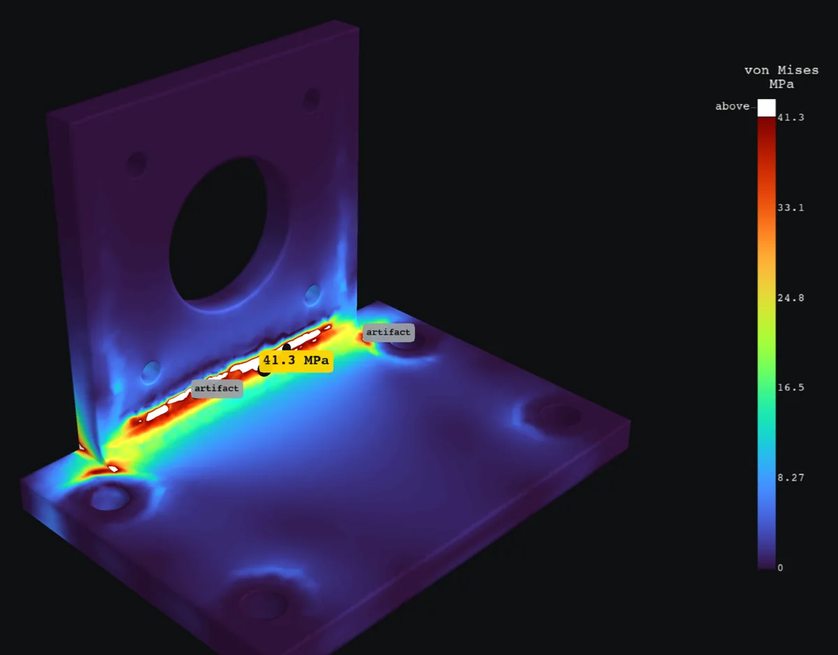
MARGINALPeak 41.3 MPa on the 3 mm inside fillet (face 3) at (-5.09, 5.11, 7.2). It survives the load, but the safety factor 1.14 is below the 2.5 target. Confidence is medium.
- Peak stress
- 41.3 MPa
- Safety factor
- 1.14
- Target
- 2.5
- Confidence
- medium
Suggested fixes
- Round the sharp inside corner to a 2.71 mm radius
- Thicken the wall at the peak from 5.41 to 8.02 mm
- Add a triangular gusset across the inside corner
summary.txt
MARGINAL. Peak 41.3 MPa on the 3 mm inside fillet (face 3) at (-5.09, 5.11, 7.2). It survives the load, but the safety factor 1.14 is below the 2.5 target. Confidence is medium. Confidence: medium. mesh convergence: von Mises stress (layer pull scaled by layer strength) still moving: 44.4 -> 41.4 -> 45.4 -> 41.3 MPa, last change 9.7% (stopped by level limit); expect about that much error; singularities: excluded from the answer: 60.4 MPa where the rigid attachment load1 grabs the part (face 13) (set by the idealized support: 56.6 -> 75.2 -> 75.1 -> 60.4 MPa); 53.1 MPa at a sharp inside corner (face 5) (a sharp corner: singular in theory, so the value depends on the mesh: 54.9 -> 52.5 -> 53.5 -> 53.1 MPa); 59.4 MPa where the rigid attachment load1 grabs the part (face 13) (set by the idealized support: 54.4 -> 55.3 -> 57.2 -> 59.4 MPa). Wobbl reports the stress 1.85 mm or more away from these spotsMax deflection 2.6 mm at (-25, 0, 55).Material PETG (3D printed), limit 47 MPa; mass 34.95 g.Loads: 250 N down at 0,-15,31 @ normal +y and box -21,4,10,21,6,52 rigid. Fixtures: bolt holes d=5.5. Checks: [warn] mesh convergence: von Mises stress (layer pull scaled by layer strength) still moving: 44.4 -> 41.4 -> 45.4 -> 41.3 MPa, last change 9.7% (stopped by level limit); expect about that much error [pass] force balance: reactions balance the loads to 0.00011% (forces) and 2.7e-05% (moments) [skip] hand calculation: no simple beam model applies (the governing point is not between the fixtures and the load, so no single section carries it) [warn] singularities: excluded from the answer: 60.4 MPa where the rigid attachment load1 grabs the part (face 13) (set by the idealized support: 56.6 -> 75.2 -> 75.1 -> 60.4 MPa); 53.1 MPa at a sharp inside corner (face 5) (a sharp corner: singular in theory, so the value depends on the mesh: 54.9 -> 52.5 -> 53.5 -> 53.1 MPa); 59.4 MPa where the rigid attachment load1 grabs the part (face 13) (set by the idealized support: 54.4 -> 55.3 -> 57.2 -> 59.4 MPa). Wobbl reports the stress 1.85 mm or more away from these spots [pass] bolt bearing: worst hole of fix1 (d 5.5 mm) carries 81 N sideways and 52.6 N along its axis; bearing stress 2.93 MPa, safety factor 16.04 on bearing [pass] units and sanity: part 102 mm across, peak strain 0.02, max deflection 2.6 mm (2.5% of size): all plausible [pass] large deflection: deflection is large next to the wall thickness, so Wobbl solved the first mesh with large deflection theory too: the peak moves +7.1% and the deflection +6.3%; linear theory holds [info] load introduction: the off part loads enter through a rigid attachment (the attached part does not flex). With a distributing coupling (the attached part adds no stiffness) instead, the governing stress converges to 73.6 MPa on face 13 at (-13.8, 4.86, 15.5) (1.8x, safety factor 0.64) over 3 meshes refined around that peak: 70.7 -> 73.1 -> 73.6 MPa, last change 0.7%. The verdict is the same either way Assumptions: - Linear elastic material and small deflections (no yielding redistribution, no buckling). - PETG (3D printed): E 2100 MPa, Poisson 0.38, von Mises vs yield 47 MPa (Prusament PETG technical data sheet). - Loads are static and applied all at once; no impact, vibration or fatigue. - Printed layers stack along z; pull across layers is judged against 70% of the in-plane strength. - Bolted holes are rigidly held over the hole and a washer sized ring (twice the hole radius). - Remote loads reach the part through a rigid attachment (the attached part does not flex). - Contact between separate parts, friction and preload are not modeled. Suggested fixes: - Stress piles up in the sharp inside corner. A fillet of 2.71 mm (about half the 5.41 mm wall) spreads it out. - The wall through the peak is 5.41 mm. To reach safety factor 2.5 it needs 8.02 mm (+48%), because bending stress falls with thickness squared. - The peak sits where two walls meet and bend. A gusset as thick as the wall, with legs about half as long as the shorter wall, ties them together and usually cuts the corner stress by half or more. Images: stress: images/stress.png, zoom: images/zoom.png, safety: images/safety.png, deformed: images/deformed.png, convergence: images/convergence.pngReport: report.htmlAbout this example
This NEMA 17 stepper mount is printed in PETG with 5 mm walls and bolted down through four
holes. The motor’s face presses on the upright, its pulley sits 15 mm behind it, and the belt
pulls 250 N straight down. The same part is run with its two 4 mm ribs and without them
(--param rib=0). Printed layers stack along z, so pull across the layers is judged against
the weaker layer strength.
| Version | Peak stress | Safety factor (target 2.5) | Verdict |
|---|---|---|---|
| With ribs | 11.0 MPa | 4.3 | holds |
| Without ribs | 41.3 MPa on the 3 mm fillet at the upright’s base | 1.14 | marginal, since it survives once with no margin for a printed part |
The ribs cut the peak stress by nearly a factor of four. Wobbl also tells you what the answer leans on.
- The motor face is modeled as rigid. If the flange were flexible enough to spread the load evenly, the ribbed mount would see 18.8 MPa (safety factor 2.50, a hair under the target) and the bare one 73.6 MPa, each converged over three meshes refined around its own peak. For the ribbed version that sits right at the target, so the result is marked medium confidence with that reason.
- The edges of the bolted washer rings and of the rigid motor face read up to 54 MPa and climb as the mesh refines. Those are artifacts of perfectly rigid supports, so Wobbl lists them and reports the stress away from them.
- The fillet peak still moves between meshes, through 11.1, 10.3 and 11.0 MPa with ribs and 45.4 and 41.3 MPa without, so Wobbl reports the last change, 6.6% and 9.7%, as the likely error. With ribs the verdict holds even at the highest value seen, and without them every mesh’s value is marginal.
Run it yourself
$ git clone https://github.com/sohan-bhat/wobbl$ cd wobbl/examples/motor-mount && ./run.shThe part, the script and every output are in examples/motor-mount on GitHub.