
Cast motor mount
Does a cast motor mount meet a safety factor of 2 under a 2 kN belt pull?
You ask
Does this cast motor mount meet our safety factor 2 rule under a 2 kN emergency stop belt pull?
Wobbl runs
$ wobbl run "../../src/wobbl/validation/parts/cast_motor_mount.step" \ -m "custom:E=72400,nu=0.33,yield=165,process=cast" --target-sf 2 \ --fix "z=min" \ --load "2000 N -0.8660254,0,-0.5 at 0,-30,66 @ holes d=6.6" \ --budget 600Checks
- passmesh convergence
- passforce balance
- passsingularities
- passunits and sanity
- warnload introduction
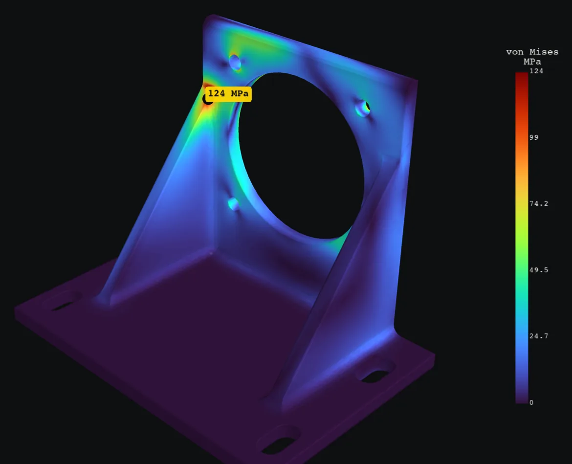
MARGINALPeak 124 MPa on the 3.99 mm inside fillet (face 65) at (43.9, 8.96, 79.6). It survives the load, but the safety factor 1.33 is below the 2 target. Confidence is medium.
- Peak stress
- 124 MPa
- Safety factor
- 1.33
- Target
- 2
- Confidence
- medium
Suggested fixes
- Thicken the wall at the peak from 6 to 7.35 mm
- Add a triangular gusset across the inside corner
- Switch to Aluminum 6061-T6
summary.txt
MARGINAL. Peak 124 MPa on the 3.99 mm inside fillet (face 65) at (43.9, 8.96, 79.6). It survives the load, but the safety factor 1.33 is below the 2 target. Confidence is medium. Confidence: medium. load introduction: the off part loads enter through a distributing coupling (the attached part adds no stiffness). With a rigid attachment (the attached part does not flex) instead, the governing stress converges to 55 MPa on face 2 at (-34, 0, 29.5) (0.44x, safety factor 3.00) over 3 meshes refined around that peak: 54.2 -> 54.3 -> 55 MPa, last change 1.1%. The verdict depends on this assumption: check how the attached part really carries the load; the verdict depends on how the load enters the part (rigid attachment versus distributed); the answer assumes distributedMax deflection 0.265 mm at (24.2, 0, 112).Material Custom material (cast), limit 165 MPa; mass 359 g.Loads: 2000 N -0.8660254,0,-0.5 at 0,-30,66 @ holes d=6.6. Fixtures: fixed z=min. Checks: [pass] mesh convergence: von Mises stress settled: 122 -> 124 -> 124 MPa over 3 meshes, last change 0.1% [pass] force balance: reactions balance the loads to 1e-05% (forces) and 1.2e-06% (moments) [skip] hand calculation: no simple beam model applies (the governing point is not between the fixtures and the load, so no single section carries it) [pass] singularities: no sharp corner or support artifact is above the reported stress [pass] units and sanity: part 203 mm across, peak strain 0.0017, max deflection 0.265 mm (0.13% of size): all plausible [warn] load introduction: the off part loads enter through a distributing coupling (the attached part adds no stiffness). With a rigid attachment (the attached part does not flex) instead, the governing stress converges to 55 MPa on face 2 at (-34, 0, 29.5) (0.44x, safety factor 3.00) over 3 meshes refined around that peak: 54.2 -> 54.3 -> 55 MPa, last change 1.1%. The verdict depends on this assumption: check how the attached part really carries the load Assumptions: - Linear elastic material and small deflections (no yielding redistribution, no buckling). - Custom material (cast): E 72400 MPa, Poisson 0.33, von Mises vs yield 165 MPa (user supplied; the rest from Aluminum A356-T6 (sand cast)). - Loads are static and applied all at once; no impact, vibration or fatigue. - Cast part treated as sound and uniform; porosity or shrinkage in thick sections can lower the real strength, which is why castings carry larger safety factors. - Fixed faces are perfectly rigid; real mounts flex a little, which lowers peak stress next to them. - Remote loads and moments are spread over their faces without stiffening them. - Contact between separate parts, friction and preload are not modeled. Suggested fixes: - The wall through the peak is 6 mm. To reach safety factor 2 it needs 7.35 mm (+22%), because bending stress falls with thickness squared. - The peak sits where two walls meet and bend. A gusset as thick as the wall, with legs about half as long as the shorter wall, ties them together and usually cuts the corner stress by half or more. - Stress stays about the same for the same shape and load, so Aluminum 6061-T6 (276 MPa) gives safety factor 2.23. It is 0.95x as stiff, so deflection scales by 1.05. Other options: Mild steel (ASTM A36) (2.02), Aluminum 7075-T6 (4.07). Images: stress: images/stress.png, zoom: images/zoom.png, safety: images/safety.png, deformed: images/deformed.png, convergence: images/convergence.pngReport: report.htmlAbout this example
This is a sand cast A356-T6 aluminum mount for a servo driving a conveyor belt, with a yield strength of 165 MPa and a house rule of safety factor 2 on yield for castings because of porosity. The base bolts flat to a steel frame, and the servo bolts to the upright with four M6 bolts. Its pulley sits 30 mm behind the upright, and an emergency stop pulls the belt with 2 kN, 30 degrees below horizontal. This is one of the parts a coding agent working alone could not answer in 15 minutes in the bake-off.
| Result | Value |
|---|---|
| Peak stress | 123.7 MPa where the +X rib tip meets the upright, and the reference model gives 124.3 MPa at the same spot |
| Safety factor | 1.33, below the required 2, so Wobbl calls it marginal because the casting does not yield but fails the house rule |
| Mesh convergence | 122.2, 123.6, 123.7 MPa over three meshes |
| Rigid servo case | 54.2, 54.3, 55.0 MPa over three meshes refined around its own peak, safety factor 3.00 |
| Equilibrium | forces balance to 0.00001%, moments to 0.000001% |
| Time | 5 minutes in all on a 2018 six core laptop, the rigid servo case included |
| Repeatability | four runs back to back gave these numbers to the last digit |
The answer depends on how the servo carries the load, and Wobbl says so. The belt pull is a force at a point off the part, and Wobbl’s default spreads it over the four bolt holes without adding stiffness, the way a bolt group shares a load. Treating the servo body as rigid instead moves the peak to the face the servo bolts against, about 2 mm outside a lower bolt hole, where it converges to 55.0 MPa with a safety factor of 3.00, which passes. Wobbl solves both, refines the rigid case around its own peak until it settles, reports the spread and marks the result medium confidence with that reason. A servo flange on four bolts behaves much closer to the bolt group in practice, so the part should be redesigned with thicker ribs or a larger blend at the rib tip.
Run it yourself
$ git clone https://github.com/sohan-bhat/wobbl$ cd wobbl/examples/cast-motor-mount && ./run.shThe part, the script and every output are in examples/cast-motor-mount on GitHub.